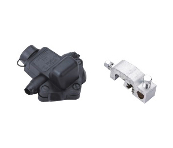
| Insulated piercing connector |
 |
Material:High strength aluminium alloy, anti-UV plastic
A broad usage in the low voltage insulation lines,leading the branch connection to the main conductor. T-connection of low voltage insulation wire service and cable branch connection for building distribution system.The material for the inside body is high strength aluminum alloy, and the insulation cover is used polyvinyl chloride(PVC). The connectors with specially designed contact teeth,are suitable for the connection of aluminum. Put the main conductor and branch conductor parllel into the teeth grooves of the clamp, tighten the bolts,pierce the insulation of two conductors to make the conductors connect.
The insulation cover functions as waterproof and sealing perfectly.
At the breaking force of the conductor, the connector will not be distorted and broken. At the rated current and short circuit, rising temperature of the connector shoule be less than the connecting conductor. |
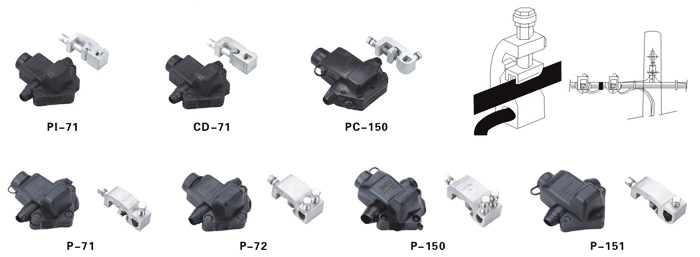
| Modle |
Main Conductor Cross-section(mm2) |
Tap Conductor Cross-section(mm2) |
| PI-71 |
35-95 |
4-54 |
| CD-71 |
35-95 |
4-54 |
| PC-150 |
35-150 |
4-50 |
| P-71 |
35-95 |
4-50 |
| P-72 |
35-95 |
2~(4-50) |
| P-150 |
70-150 |
2~(4-54) |
| P-151 |
16-150 |
6-95 | |
| Insulated piercing connector |
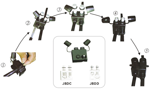 |
Material:High strength aluminium alloy,anti-UV plastic
Product property:JBDC and JBDD series products have more functions than JBD.
JBDC is to lead the branch from the bare main line,while JBDD is to lead the branch from the insulated main line.Tighten the bolt with an idealtorque,which ensures the best quality of connection. |
| Modle |
Bare Main Conductor Cross-section(mm2) |
Insulated Branch Conductor Cross-section(mm2) |
| JBDC6-35/6-35 |
6-35 |
6-35 |
| JBDC50-150/6-35 |
50-150 |
6-35 |
| JBDC50-150/35-95 |
50-150 |
35-95 | |
| |
| Modle |
Insulated Main Conductor Cross-section(mm2) |
Bare Branch Conductor Cross-section(mm2) |
| JBDC6-35/6-35 |
6-35 |
6-35 |
| JBDC50-150/6-35 |
50-150 |
6-35 |
| JBDC50-150/35-95 |
50-150 |
35-95 | |
| Insulated piercing connector |
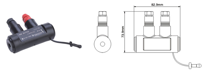 |
| Modle |
Conductor range (mm2) |
Torque(N,m) |
Insulator Endurance(6KV,1min) |
Ageing Test(salt spray) |
| SM35-P35 |
10-16 |
10 |
OK |
OK | |
| |
| Simple installation |
I-INSTALLATION
,There is no need to adjust the pre-positioned shearhead bolts prior to assembly.
,If required, strip the conductor to the length specified on the connector.
,Begin the assemblywith the dead conductor.
,Insert each conductor fully along the axis of the connector.Hold the conductor in place whilst pre-tightening the shearhead bolts to locate the cable.
For Installation under load(max.90A)("RED"side only)
,Secure the connector with the 1st conductor installed, to the ABC bundle with tape or a cable tie.
,Secure the electrical contact between the stripped conductor and the end of the adaptor during the tightening.
,To complete the installation,tighten the shearhead bolt untill breaks off.
Å-DISMANTLING "RED" SIDE ONLY
,The connector can be removed, off load. for the side by use 2nd remaining hex head.
,To remove under load, cut the conductor approx, 1 cm from the connector, using an appropriate cable cutter. Then lose the "red" screw and remove the remainingsection.
,Use the plug provided to reseal the connector.
‰-REINSTALLATION "RED" SIDE ONLY
,Strip the conductor to the length specified on the connector.
,Insert the stripped end of the conductor into the connector, as instructed in section1.
,To complete the installation, tighten the hex head bolt to the torque level specified on the connector.
♯-CAUTION(SM35-P35)
,Care should be taken to ensure that the correctly prepared conductor is inserted into the correct end of the connector.
,"RED"load making sied for stripped conductor.
,"LACK"insulation piercing for un-stripped conductor. |